The cleanliness, lighting, temperature and humidity, and quality of the air we breathe can significantly affect our performance and thus the quality of output of processes with which we work.Many of these same items are subject to the plant’s methods (how-to-do-it) and measurement (accuracy of control), so measurement is a major factor, even though it did not appear on the list.Temperature within the machine, conveyor speed and angle, solder wave height, and so on, are really the methods (usually published procedures and instructions) used in the process.The list includes many items such as parts, solder, flux, boards, and so on, and these can be collected under the word materials, which also appears on the list.The operators who prepare the boards and run the solder machine are also major factors.The solder machine itself is a major factor in the process.Six major groupings of causes are discernible listed as follows: Examine Figure 15.7 to see whether the major causes can be identified. The lower level factors affecting the major factors branch off the ribs. The ribs are normally assigned to the causes considered to be major factors. Each of the ribs represents a cause leading to the effect. The effect is the “problem” we are interested in-in this case, machine soldering defects. Ishikawa’s genius was to develop a means by which these random ideas might be organized to show relationships and to help people make intelligent choices.įigure 15.8 is a basic cause-and-effect diagram. This is where the cause-and-effect diagram comes into play. Unfortunately, the list does nothing in terms of suggesting which of the 35 factors might be major causes, which might be minor causes, and how they might relate to each other.
ISHIKAWA DIAGRAM MACHINE VS MATERIAL PC
The group developed a fairly comprehensive list of factors in the PC board manufacturing process-factors that could cause the effect of solder defects. The group uses brainstorming to generate the list of possible causes. The group is told that the issue to be discussed is the solder defect rate and that the objective is to list all the factors in the process that could possibly have an impact on the defect rate. All the groups in the plant who have anything at all to do with PC boards are represented, which is necessary to get the broadest possible view of the factors that might affect the process output. The group is made up of engineers, solder machine operators, inspectors, buyers of materials, production control specialists, and others. People at the plant decide to analyze the process to see what can be done they begin by calling together a group of people to get their thoughts. Suppose an electronics plant is experiencing soldering rejects on printed circuit (PC) boards. The cause-and-effect diagram provides a graphic view of the entire process that is easily interpreted by the brain. The same data could be tabulated in a list, but the human mind would have a much more difficult time trying to associate the factors with each other and with the total outcome of the process under investigation. This chart is simply a means of visualizing how the various factors associated with a process affect the process’s output. The cause-and-effect diagram is the only tool of the seven tools that is not based on statistics. Such diagrams can be used with any problem.Such diagrams separate causes from symptoms and force the issue of data collection.Such diagrams focus a group, thereby reducing irrelevant discussion.Creating the diagram itself is an enlightening, instructive process.

In his book Guide to Quality Control, Ishikawa explains the benefits of using cause-and-effect diagrams as follows: 3


It is also often called a fishbone diagram because that is what it looks like. Ishikawa, a noted Japanese quality expert, so sometimes the diagram is called an Ishikawa diagram.

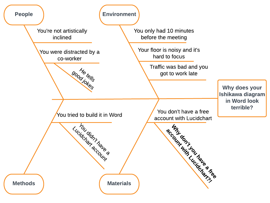
The technique was developed by the late Dr. A team typically uses a cause-and-effect diagram (see Figure 15.8) to identify and isolate causes of a problem.


 0 kommentar(er)
